

Epoxy dogbone specimen with steel fibers embedded, manufacturing and qualitative residual stress evaluation
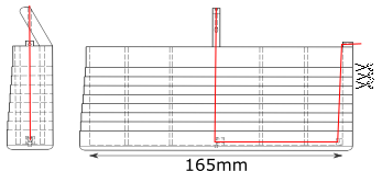
A 3D-printed mold was designed to hold 6 steel fibers (basically steel wire of 900\(\mu m\) arranged in two parallel lines of 3 fibers. The drawings show the side and front view of the mold, the red line represents one unique fiber. It is attached to the bottom of the mold using hooks that are directly 3D-printed in the mold.
Epoxy is then poured in the mold and cures around the fibers. The mold is then horizontally cut (following the scissor lines on the drawing) to provide several dogbone specimen, containing transversally embedded steel fibers. Click on the picture and move your mouse around to change the focus point and perspective.
One of the specimens was polished, then covered with light polarizing film on the front and back to reveal the photoelastic properties of Epoxy. If you ever need polarizing film, you can either buy some but it is quite hard to find large sheets. You can also get high quality filters by taking an old LCD computer monitor apart (that is what I did here), it is an easy operation that still needs you to be slightly careful (a tutorial to do so). Other surfaces were covered with black ink (Sharpy) to avoid non-polarized light diminushing the contrast of polarized light. It is then possible to qualitatively see the residual stresses in the specimen due to cooling after curing and the mismatch of coefficient of thermal expansion between the fibers and the matrix.
The density of fringes (isolines of same colours) qualitatively shows the stress concentration. The more colours there are in an area, the higher the stress concentration is. It is possible to distinguish the residual stresses due to the interaction with the mold and the residual stress around each fiber.
If you liked this post, you can share it with your followers or follow me on Twitter!