

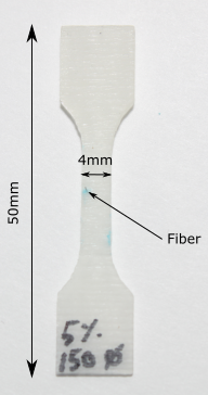
Photoelastic view of dogbone specimen containing bundle of Carbon Fibers
I manufactured a standard dogbone specimen similar to the one shown in the picture below sometime last year. Instead of using a plain monofiber, I decided to embed a Carbon Fiber (CF) bundle in it. I found some CF in our laboratory at Polytechnique and worked on a method to manufacture the specimen I had in mind.
The setup used here is the same as the one presented in the post Optical microscope Digital Image Correlation. In the GIF clip above, the specimen is shown first, and the bundle of carbon fiber going through it are indicated with a metallic ruler I am holding. The next scene shows the microtensile testing rig installed under the Olympus confocal laser microscope, a specimen is shown while being tested. In the final scene, the computer screen plugged to the microscope is shown. It is possible to see a PTFE fiber in an epoxy matrice while interfacial debonding it starting to happen. That was the specimen I was testing at the moment I shot this clip.
The specimen was loaded in the microtensile testing machine, the whole rig is put under the confocal laser microscope after what the test started. These kind of tests take about 8 hours long: the specimen is loaded displacement by pulling on the microtensile testing machine by a step inferior to (\(100 \mu m \), the microtensile testing machine is then stopped and a picture is snapped with the confocal laser (a single picture takes about 3 minutes because of the confocal scanning process). The specimen is then pulled again and these steps are repeated until a crack is observed. The purpose of this test is to observe crack initiation and propagation inside a bundle of CF. For this specimen, I stopped the test when the crack was large enough to cover the whole field of view, but before it broke the specimen in two separate parts. I then used some photoelastic film again (similar to the one presented in this post) and glued it on both sides of the specimen. The photoelastic film reveals the strain field within a polymer, the more fringes are visible in an area the higher the strian field is (more explanation were provided in this post).
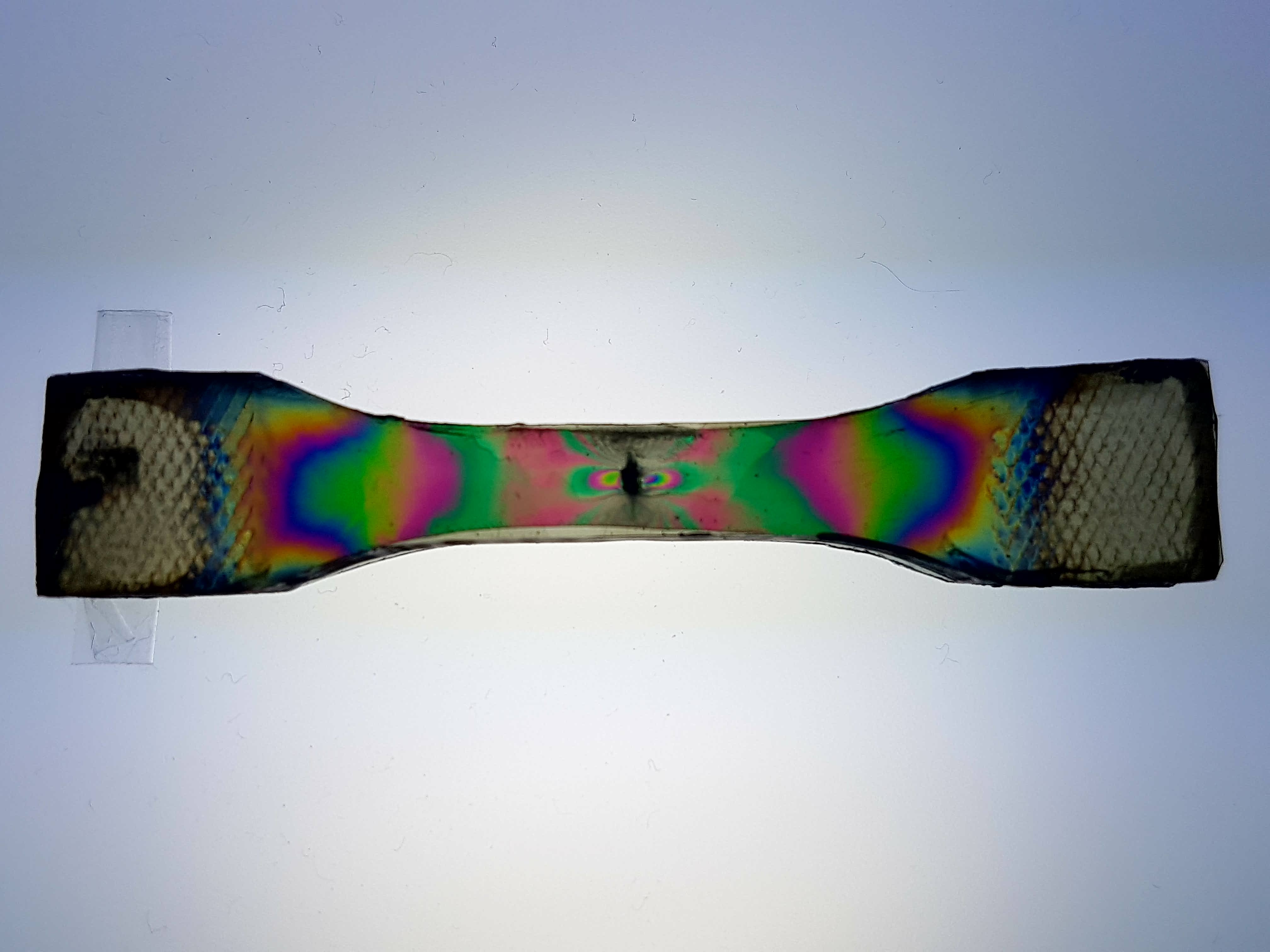
The result reveals the residual stresses remaining in the specimen after this test. It is possible to see how the CF bundle affected the strain field in its vicinity. The final purpose of this experiment is to somehow come up with a method to perform DIC on the images obtained using the confocal laser microscope.
These experiments were done with the help of Damien Texier and were done at École de Technologie Supérieur, Montréal.
If you liked this post, you can share it with your followers or follow me on Twitter!